
MAGMA Midi Synth Controller.
lire l'article en français
Contents
- 1. Introduction
- 2. Recycling an old keyboard
- 3. Designing the control panels
- 3.1. Retro Synth on MainStage
- 3.2. Main control panel
- 3.3. Wheels and octave panel
- 3.4. Back panel
- 3.5. Prints
- 4. Modeling on SketchUp
- 5. Let's build it!
- 5.1. Plexiglas panel and case
- 5.2. Solid wood frame
- 5.3. Plywood frame
- 5.4. Installing the keyboard
- 5.5. Pitch and Modulation wheels
- 5.6. Back panel
- 5.7. Wiring
- 5.8. Adding the backlight
- 6. Electronics: how it works
- 7. Programming!
- 8. That's it! ? Final product
- 8.1. Various pictures of the MAGMA in its natural habitat
- 8.2. Time consumption of the whole project
- 8.3. How much did it cost?
- 8.4. Does it worth it?
- 8.5. Demo in Video
- 9. Next things to do
- Appendix A: an homemade FlightCase, of course!
- Appendix B: some original drawings
1. Introduction
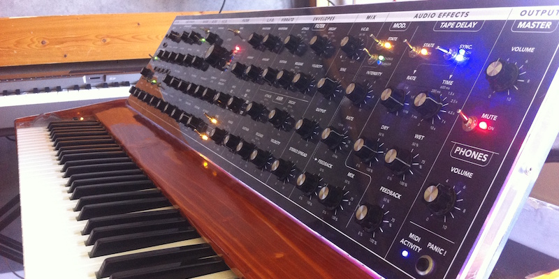
For my last year of jazz piano studies at Saint-Ãtienne's Conservatory (France), I created a band project with some friends. But I wanted a synthesizer in order to stretch out the audio spectrum of my sounds, generally playing on an acoustic piano. But synths aren't cheap at all. Especially those used in jazz ? the MiniMoog... Since I didn't have such money to spend on that, I decided to make a MIDI controller to plug into MainStage on MacOS, which has killer replicas of vintage synths. I specify that I'm just a computer scientist who do woodworking and reaaaaly basic electronics on my free time ? I'm not an electronic genius, I just like to mess around with the Arduino. PS: The name that I gave to this controller comes from my all time favorite band Magma.2. Recycling an old keyboard
Here is the naked old keyboard that I used for this project, recycled from a Casio whatever-the-name with really bad sounds. Maybe It was used for children to learn piano two decades from now ? whatever, the touch was pretty close to synthesizer's one, plus it has a nice built-in MIDI-out port that I kept. The original recycled keyboard.
3. Designing the control panels
3.1. Retro Synth on MainStage
First, let me briefly introduce you the so-called 'Retro Synth' VST (or probably an AU) on MainStage that I used before I even had the idea to make this project, first controlled by my good old vintage Yamaha DX7.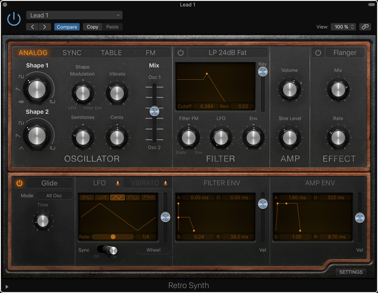 View of the nice 'Retro Synth' in MainStage
3.2. Main control panel
I designed the control panel on an app called 'Graphics'. The hardest and longest thing to do was to decide which controls to put at which place. I ended up using every control assigned to the VST, plus some other. Here is the order of the layout from left to right:- SYSTEM: patch, tempo
- MODULATION: kind of a modular way to plug wheels and velocity onto other controls
- MIDI EFFECTS: an convenient arpeggiator, a pitch / velocity randomizer and a transpose unit
- VOICES: number of voices, tuning, pitch bend
- GLIDE: the glissando effect if you're on legato mode
- V.C.O.: two oscillators with different wave shapes and tuning
- FILTER: what makes the beauty of the Minimoog sound
- L.F.O: low frequency oscillator controlling the filter
- VIBRATO: actually a second L.F.O., controlling the pitch
- ENVELOPES: one for the filter, and one for the amplitude
- MIX: you can actually add the basic Sine as a third oscillator, plus mixing the two others
- AUDIO EFFECTS: Flanger, Chorus, Delay (The overdrive didn't interested me much as the time, I kind of regret now that I didn't add it on the panel)
- OUTPUT: a master volume and mute (outputs 3-4 on my sound interface) and a phone volume (outputs 1-2)
- PANIC! button in order to kill every resident MIDI signal in case of a (rare) glitch
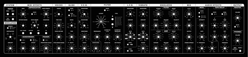 The main control panel
3.3. Wheels and octave panel
Like on a large amount of synthesizers, the need of the pitch and modulation wheels is pretty obvious if you want to add expressivity to your play. This is why I designed a small panel who will stand on the left of the keyboard. I also added an octave shifter in a form of two buttons and five indicative LEDs.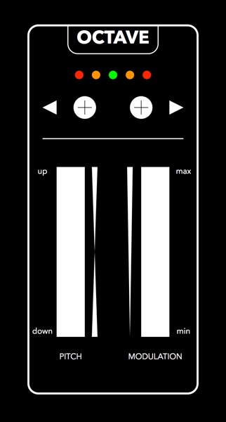 The octave / wheels panel
3.4. Back panel
The MAGMA has the following inputs / outputs, located on the back of the case:- Sustain Pedal
- PedalBoard Input (will be described on an other article)
- Keyboard MIDI out
- Controls MIDI out
- D.C. 12V
 The back panel
3.5. Prints
Once I was 100% sure of the last-ultimate-final version of the panels, I get to a local print shop and ordered a full sized paper-print of these. Here is what it looked like, with the potentiometer caps I ordered. The printed panel
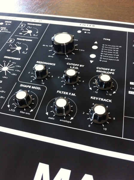 The printed panel with pot. caps
4. Modeling on SketchUp
I you're reading this and you work at the local print shop I talked a few lines above, maybe it's your fault if my synth is actually a little bit smaller that intended. Indeed, I didn't brought a tape measure to check if the dimensions of the panels was 100% accurate; but i should have. The main panel you saw was supposed to be exactly 970 mm wide, but the print is around 930. Which means that I had to shrink the octave and wheels panel down by 5 cm. I suppose it's not such a bad thing since it's pretty comfortable to the left hand not to have a bigger space between the two wheels. But I'm still mad. Grrr. I designed the whole MAGMA M.S.C. on SketchUp, which allowed me to provide any details on the construction of the case.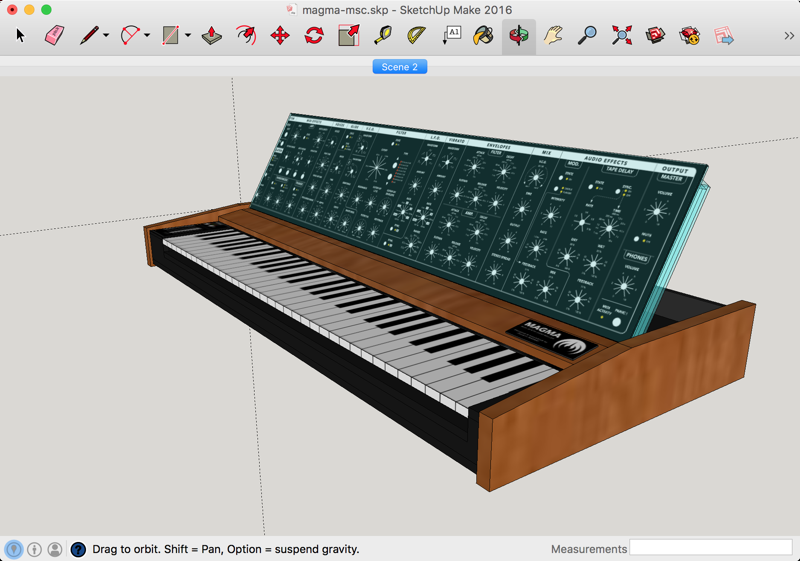 SketchUp Model - with textures
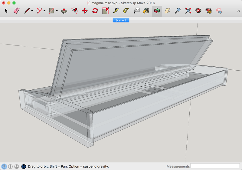 SketchUp Model - semi-transparent view
5. Let's build it!
Here is an almost detailed history of how I built the MAGMA.5.1. Plexiglas panel and case
If you take a look to the back of the control panel, you'll see that the case of it is made of Plexiglas! Why? Some time (often), people are telling me that we see all the cables and it's ugly, but the idea was precisely to make it transparent in order to see the back of the potentiometers, the Arduino and Multiplexers (that we'll see below), and the whole bunch of multicolor cables that needed no less than 800 solders by hand. I know it's messy, it's not made in a factory in China, but in my uncle's garage, and I wanted people to know the work that has be done on this controller. Plus, with the animated LEDs, it's just marvelous. ;-)Whatever, I made this box by laying out the 2mm Plexiglas on top of the printed panel to draw the exact dimensions, then cutting two same rectangles, which will take the print in sandwich. Then I had to plane the sides of them because table saw gives really raw and ugly results on this material.
 Drawing the exact dimensions
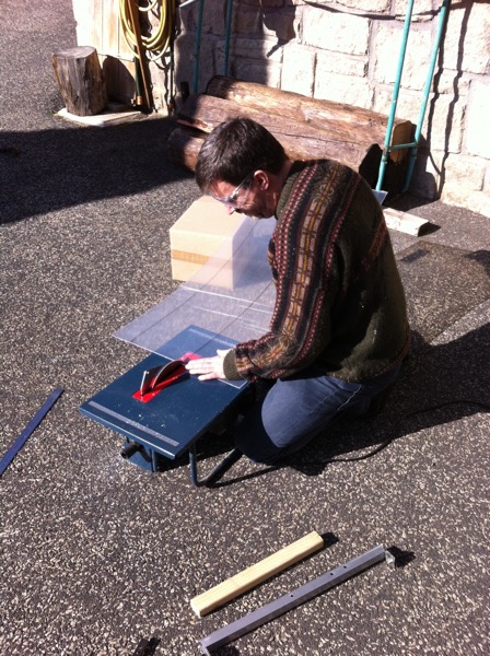 My uncle cutting the the Plexiglas
 Remember to always protect your ears and eyes!
 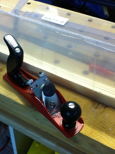 Planing the sides of the Plexiglas sheets
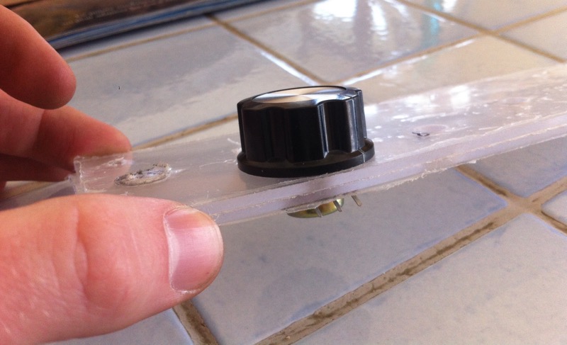 Two Plexiglas sheets clamped together by a potentiometer (and my big fat pianist fingers).
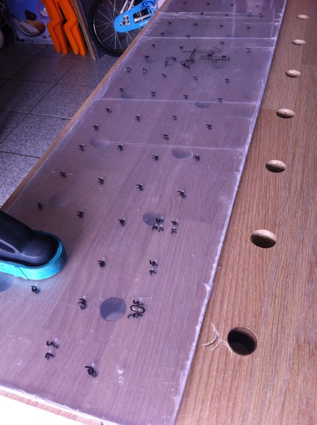 Laying out the holes positions
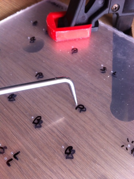 Punching softly the holes for a more precise drilling
 Drilling vertically using this convenient plunging adapter
 Laying out the PCBs (see bellow). You can see the holes.
 Drilling holes through aluminum and Plexiglas
 A view of the angles in the corner of the box
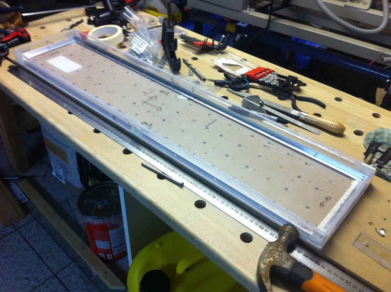 The whole "bottom" box ready to be riveted
 A rivet who will be installed soon
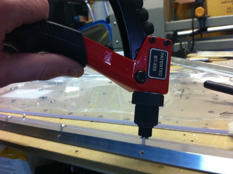 Riveting on the corner
 The control panel with the potentiometers installed
 A piece of tubing preventing the PCB rail to touch the potentiometers
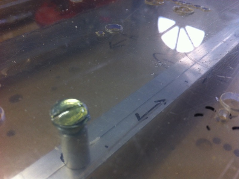 The PCB rail under the front panel, attached with the machine screw though the tube
5.2. Solid wood frame
The frame is built with solid spruce that my uncle gave me, on which I applied several coats of a wildness "exotic wood" varnish and a glossy finish for more sexyness.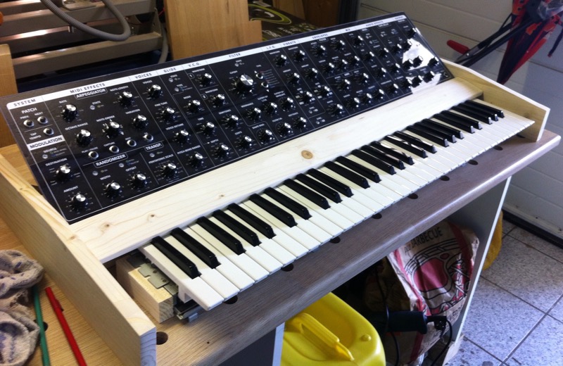 First time with the solid frame in place
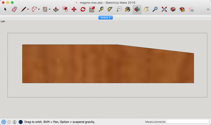 The left wooden side
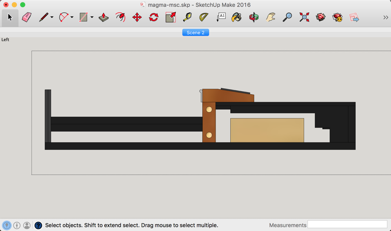 The internal wooden structure seen from the left
 We can see the crossing board in the middle
 I used three different sandpapers, and since I had three sanders on hand...
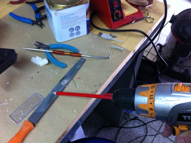 How to sharpen a pencil with a drill...
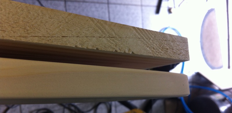 Before / after sanding
 A side board after a first coat of varnish and a fine sanding
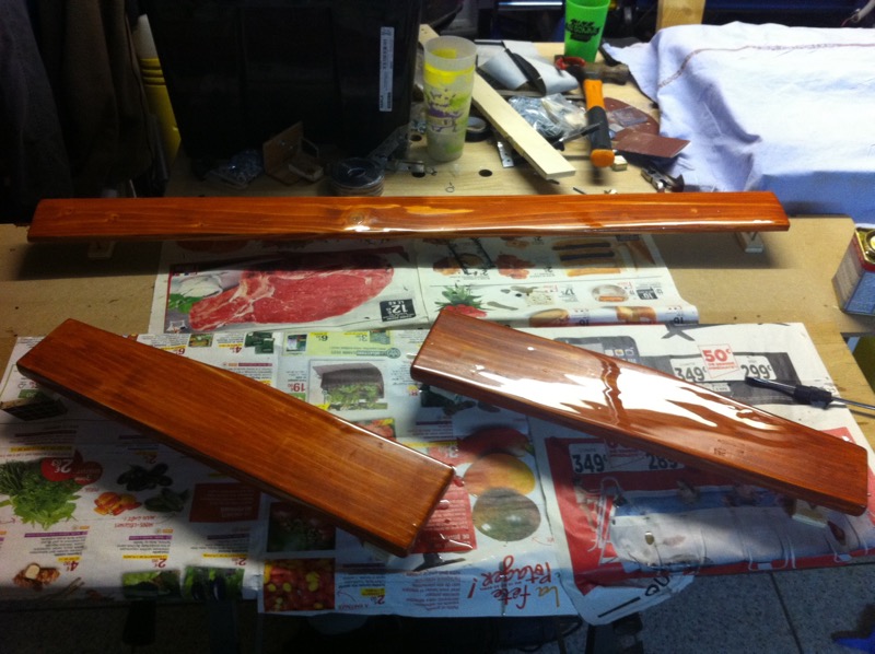 The three spruce boards after the final coat of varnish.
5.3. Plywood frame
 The front part being clamped down, ready to be glued and screwed in place
 A little jig to drill pilot-holes right at 5 mm from the border of the plywood
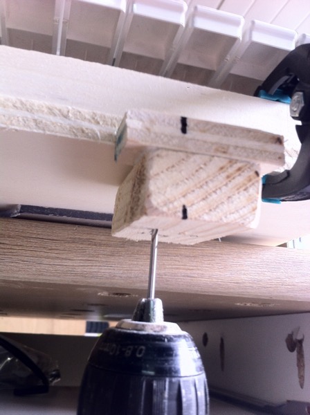 The pilot-holes jig in action
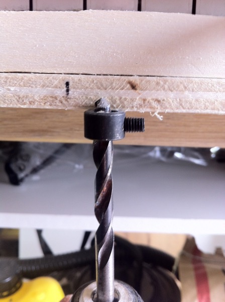 A special ring used to countersink the holes
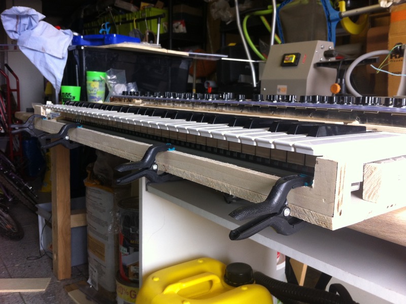
5.4. Installing the keyboard
The original old Casio's keyboard has a very strong metallic frame that was used to be attached onto the plastic mold. I had to make little blocks in order to fit the keyboard perfectly into the wooden case.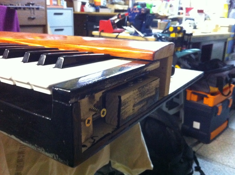 How is screwed the right part of the keyboard
5.5. Pitch and Modulation wheels
First I had to cut the Plexiglas for the octave / wheels panel. You will absolutely need some kind of multi-tool or a scroll-saw to do this step.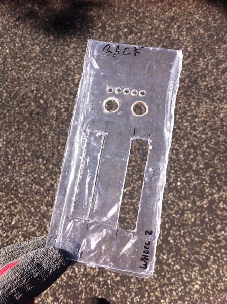 The octave / wheels panel cut in the Plexiglas (not on the left)
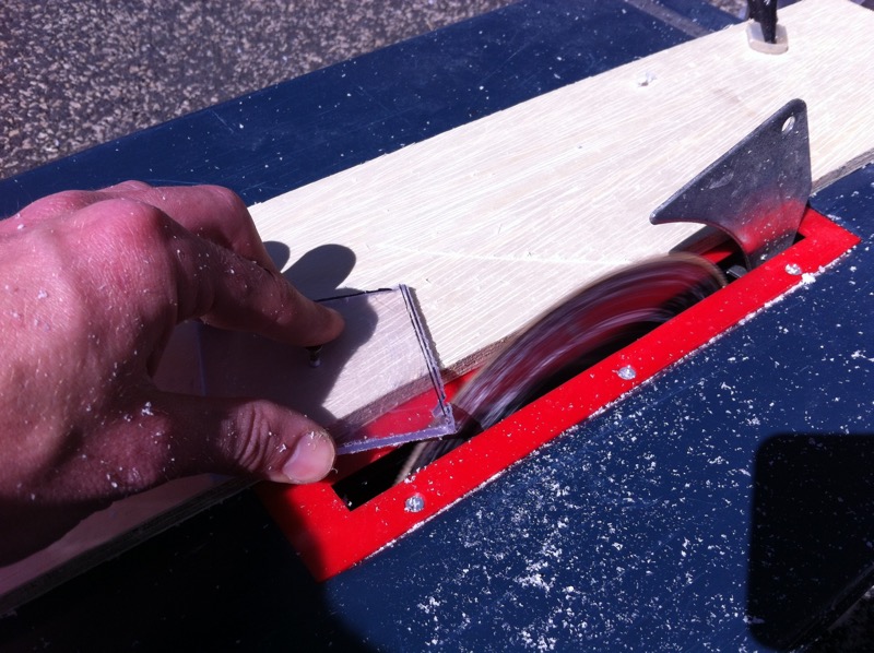 First cutting small parts of the square...
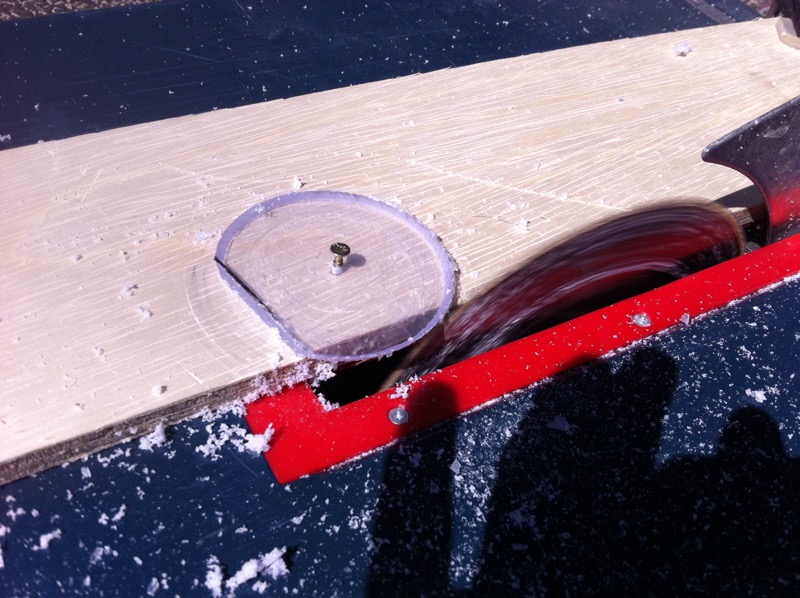 ... and gradually moving towards the blade
 The octave / wheels panel
5.6. Back panel
5.7. Wiring
Internal wiring:- switches and push buttons: connect one pin to 5V, multiplexing the output from the other pin (you will probably need pull-up resistors)
- potentiometers: connect 5V and GND (ground) to the opposite pins, multiplexing the output from the middle pin
- LEDs associated to buttons: directly connect them on the output of the switches via a 220? resistor and GND
- LEDs for the octave and filter type: de-multiplexed from 2 differents CD4051 (the multiplexing / de-multiplexing chip, see next section)
- Pitch and Modulation wheels: they are regular potentiometers
- CD4051: the mux / demux are connected to the Arduino
- LEDs backlight [optional]: independent circuit
- Sustain Pedal: in my case I simply soldered the socket as an extension of the one built in the original keyboard
- MIDI output: connected to a TX (transmit) port of the Arduino
- MIDI keyboard output: connected directly to the MIDI output of the original keyboard
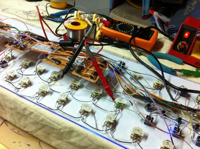 My workspace during the long process of cutting, stripping and soldering a lot and a lot of wires.
(((60 pots + 2 wheels) * 3 pins) + (27 buttons * 2 pins) + (26 LEDs * 2 pins)) * (2 extremities of cable) = 584 solders [1]
.
Of course we can add the multiplexing:
((8 mux for pots LEV1) + (4 mux for buttons) + (1 mux for pots LEV2) + (2 mux for LEDs)) * (16 pins) = 240 solders. [2]
And obviously the arduino I/O:
(3 * 4 mux pins) + (6 * 1 inputs) + (1 * VCC) + (1 * GND) = 20 solders on the Arduino [3]
Which gives us a total of:
[1] + [2] + [3] = 584 + 240 + 20 = 844 solders.
And now, if we take in account the time of cutting (~1s), stripping (~2s), placing (~1s) and soldering (~1s) the wires, we get:
844 solders * 5 seconds = 4220 seconds = 1h 10m 20s
Of course, it took way longer than that (I spent all night from 9PM to 6AM to to all the soldering), because I had to check everything, and this takes a very long time.
Here is a video about checking the switches positions using the Arduino and the multiplexers:
5.8. Adding the backlight
I added the backlight a couple of months after the whole projects was done (at least I thought so), and didn't took any picture during the installation. It was quite easy though: I just glued strips of RGB LEDs inside the aluminum corners of the Plexiglas control panel, which are controlled by a small unit just next to the Arduino via a small remote. Now we can see the wires better (as I wanted to), and it provides an excellent backlight to the control panel, which is more than convenient when playing on a dark stage.6. Electronics: how it works
6.1. Arduino
The Arduino board is an open-source micro-controller based on the ATMEGA128 or ATMEGA328 chip. A smaller but as efficient version of the standard Arduino UNO, the Arduino Nano (Rev. 3) is what I used for this project. It's really simple to used, and even if you have no experience in programming, you can make some funny projects pretty quickly. If you want to learn more about it, there is a huge community of makers that shares their various ideas and problems to the others, such as the Arduino Officiel Tutorials website or (my personal favorite) the Instructables DIY tutorials website, which is really really wonderful.6.2. Multiplexing / De-multiplexing
If you know the Arduino a little bit, you'll know that there is a limited number of inputs and outputs (analog or digital). This is where multiplexing and de-multiplexing becomes necessary. Here is how it works: with 3 binary digits, you can count from 0 to 7 (000, 001, 010, 011, 100, 101, 110, 111). Now let's say that we have a chip that has 8 analog or digital inputs, and one output ; using 3 binary voltage controls A, B, C (HIGH or LOW for 1 or 0), you can select the input which will be redirected the the output of the chip. And it's exactly what does the CD4051 chip. If now, you want to light up one LED at the time among 8, you can revert the process by setting the previously called output pin to a input voltage of 5V, and then simply select which of the 8 outputs you want to pass the 5V to with three controls A, B, C.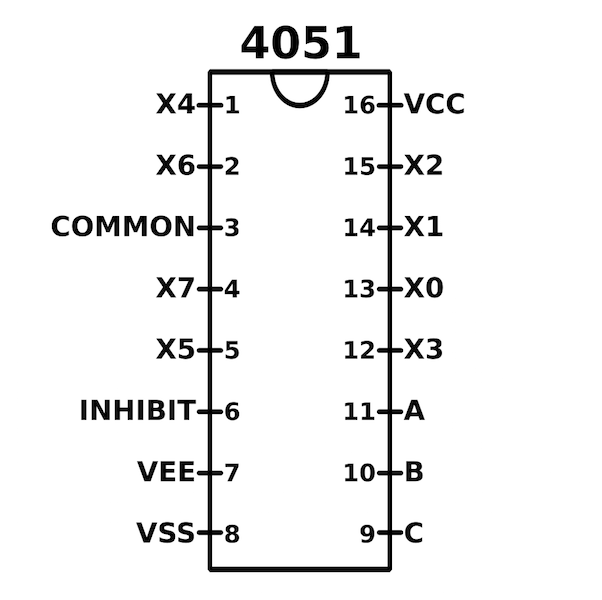 Pinout of the CD4051 chip
It's fairly simple to implement on the programmer (I do it in one line of code), but requires a bit of a headache on the soldering phase.
7. Programming!
Alright friends ! You may know that I'm actually an computer scientist, so I loved this part, and actually written all the code even before receiving all the electronic components. I'll explain the general algorithm and enter in some details by trying to be understandable by most of you.7.1. MIDI code
Let's start with the core of the whole project: the MIDI protocol. This simple way to communicate between instruments without loosing any information exists since the early 80's, and has now become a grand standard for every single musical controller (and even machine and show controls), either using the original 5-pins DIN connector, or from several years now, USB. A MIDI code is just a sequence of three consecutive bytes (8 bits):- a status byte: describes the type of the message
- a first data byte (note pitch, control-change, ...)
- a second data byte (velocity, various values)
(144 + chn, note number, velocity) for a note ON, and (128 + chn, note number, velocity) for a note OFF, with chn being the channel (0 - 15) you want to use to transmit the data. In our case, we want to control things on the computer. So we use "Control Changes" messages, defined as follows : (176 + chn, ID of the control, value of the control). Simple as that. We just have a small variation for the pitch-bend wheel : (224, 0, pitch value)
7.2. A basic algorithm
7.3. The real Arduino Code
8. That's it! ? Final product
8.1. Various pictures of the MAGMA in its natural habitat
At his home, where he lives most of the year...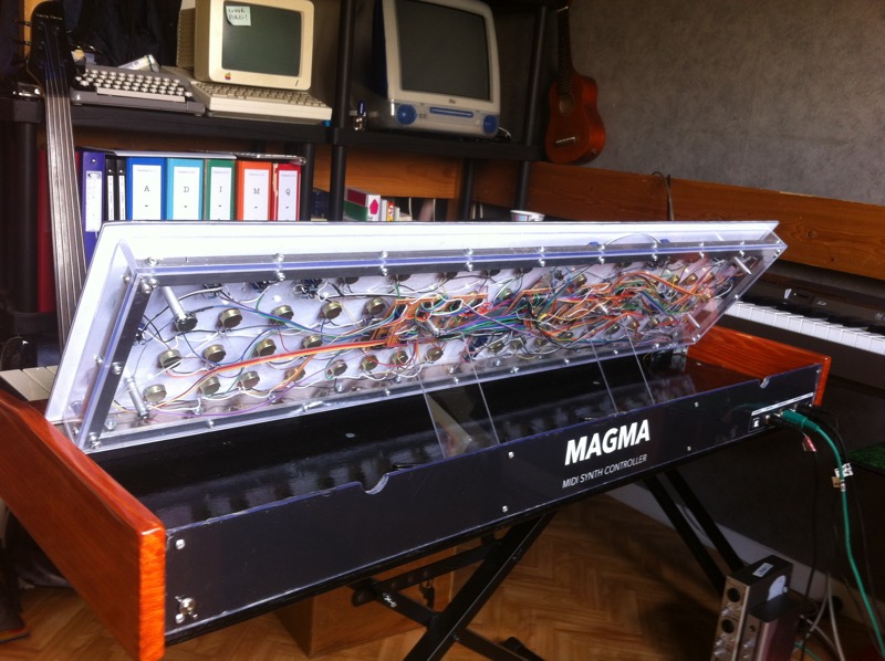 Here is the digestive system of the MAGMA
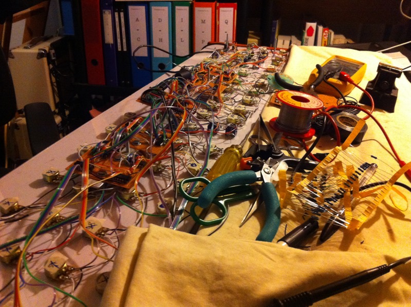 Surgery is sometimes necessary...
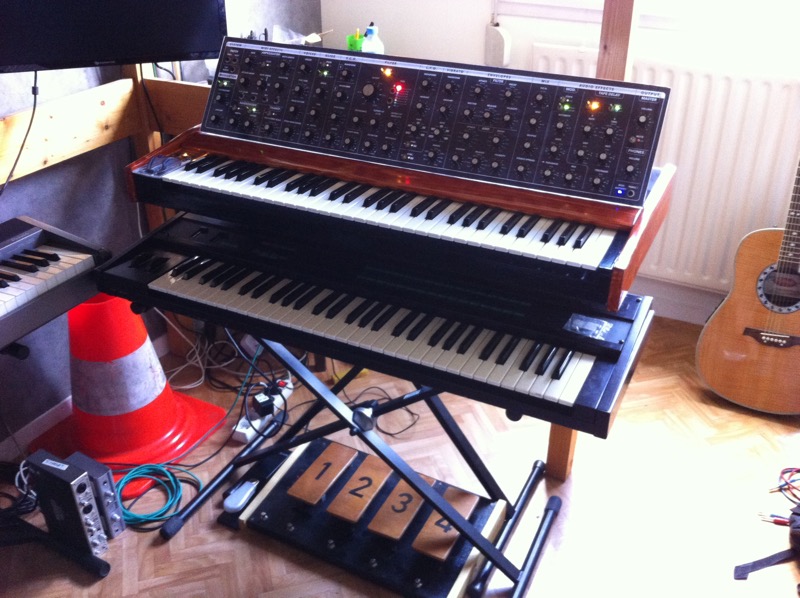 He likes to be with other synth friends.
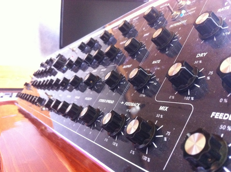 A little selfie.
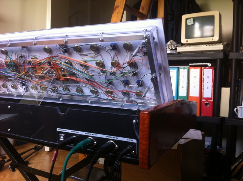 The mouth wide open, ready to talk!
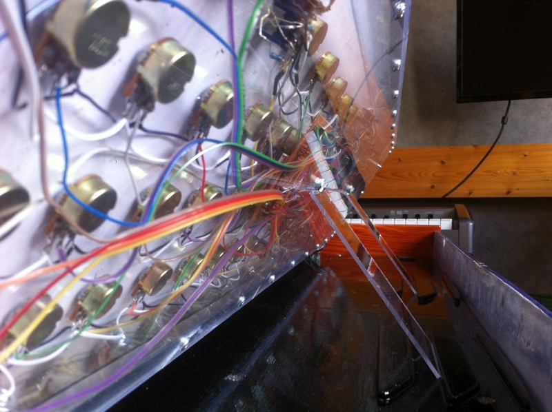 He can stand up easily on his two glassy feet.
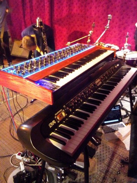 He's a little bit blueish, wonder if he's ok.
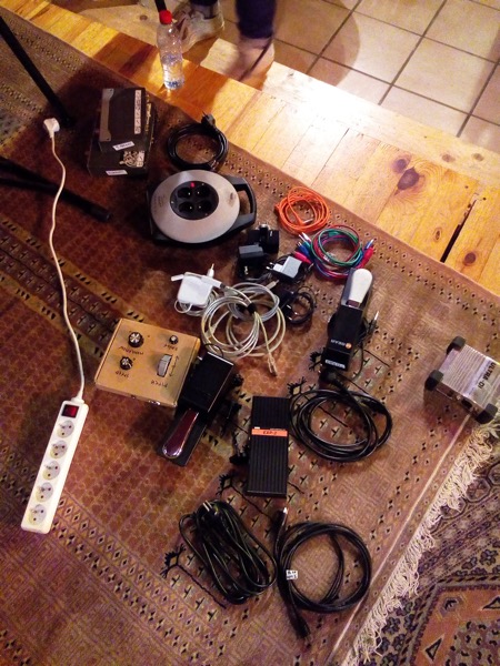 Into the wild, he needs a lot a external resources to survive
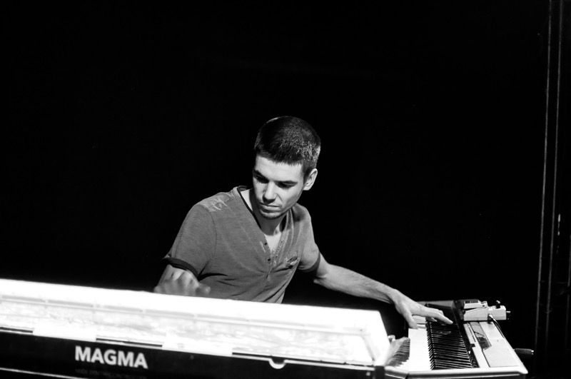 Meditating with his guru.
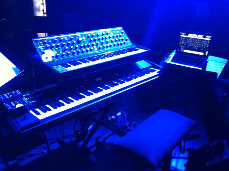 Big stage this night!
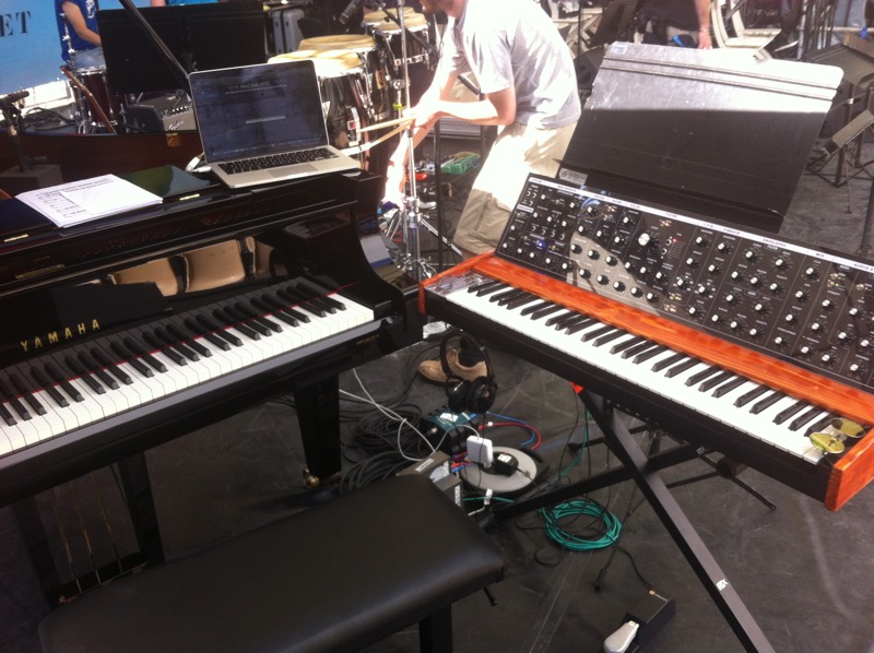 Taking a sunbath at the "Jazz à Vienne" festival...
8.2. Time consumption of the whole project
A little timeline of the built:- 2015, December 5th: first draw of the control panel
- 2016, February 11th-19th: ordering the electronic components on AliExpress
- 2016, March 25th: all the panels are finally designed
- 2016, April 23rd: the print of the panel arrived
- 2016, April 23rd: beginning of the build: Plexiglas cutting;
- 2016, May 11th: beginning of the electronic soldering (800+ solders)
- 2016, May 28th: end of the build, still some electronic glitches. Moving the MAGMA from my uncle's to home
- 2016, June, 5th: end of debugging. Ready to gig.
- 2016, June, 6th: piano jazz final exam (tight deadline!), passed an excellent grade. Yeah.
- 2017, Novembre, 20th: finally writing this article, in English
- 2017, Novembre, 21st: and translating it in French
8.3. How much did it cost?
Here is two tables detailing the material costs:| Woodworking stuff | ||||
|---|---|---|---|---|
| Articles | Dimensions | Price / pce | # Pieces | Total Price |
| ply wood | 1200 x 600 x 5 | 10.5 | 1 | 10.50 |
| plexiglas | 1000 x 500 x 2.5 | 10.6 | 2 | 21.20 |
| plexiglas | 1000 x 500 x 5 | 19.9 | 1 | 19.90 |
| piano hinge | 2000 x 32 | 3.5 | 1 | 3.50 |
| wood glue | 100g | 5.4 | 1 | 5.40 |
| dowels | 50p | 1.99 | 1 | 1.99 |
| wood screws | 3 | 1 | 3.00 | |
| Total | 65.49 | |||
| Electronics | |||
|---|---|---|---|
| Article | Price / pce | # Pieces | Total Price |
| pots | 0.167 | 64 | 10.706 |
| PCBs | 0.106 | 4 | 0.424 |
| LEDs | 0.0108 | 20 | 0.216 |
| CD4051 | 0.1335 | 13 | 1.7355 |
| USB female | 1.19 | 1 | 1.19 |
| 12v jacks | 0.197 | 1 | 0.197 |
| jacks socket | 0.42 | 2 | 0.84 |
| power supply | 0.87 | 1 | 0.87 |
| resistors | 0.0176 | 10 | 0.076 |
| Arduino Nano | 1.585 | 1 | 1.585 |
| pot caps (A02) | 0.305 | 60 | 18.34 |
| pot caps (A03) | 2 | 1 | 2 |
| pot caps (A04) | 0.317 | 1 | 0.317 |
| switches | 0.187 | 13 | 2.431 |
| flat (ribbon) wire | 6.14 | 1 | 6.14 |
| buttons | 0.0855 | 15 | 1.2825 |
| bumpers | 0.095 | 4 | 0.38 |
| totals | 197 | 47.44 | |
- the spruce board
- varnishes
- sand papers
- the keyboard
- some 12V power supplies
8.4. Does it worth it?
Yep, totally. As attended, I used it on my final jazz exam at the conservatory, and I get my diploma with a really good grade. It's not all due to the MAGMA, but I was able to make a beautiful long solo on the synth that I think people enjoyed. The jury did ;-)Moreover, I use it for every jazz and funk gigs since I built it. I can play various synths (generally basses), and even other well-sampled Rhodes, organs and clavinets, until I bought my KORG SV-1 almost two years later to play the piano and rhodes sounds.
I absolutely love it, and I hope you like the design and the idea of it!
8.5. Demo in Video
Here is a cover of the magnificent Stranger Things series O.S.T. that I make exclusively on the MAGMA M.S.C. There is any other sounds or sample. Every single note (the arpeggiators has been set off camera), 'heart-beats' and effects has been done on the MAGMA on MainStage. It gives a good idea of what I can do in real time. Hope you'll like it.9. Next things to do
- As I mentioned somewhere, I have a MIDI PedalBoard built on the same principle, but much simpler. It was kind of a prototype of the MAGMA. The thing is that Arduino boards are capable of communicating, via Serial messages. Which means that I could plug this PedalBoard into the Magma to controls some pots or buttons. I never had so much utility to do that, but the USB port to receive the PedalBoard in built in the MAGMA back panel. Could be fun sometime.
- When I will receive my Teensy 3.2 board (a more advanced, powerful and faster version of an Arduino), I'll try to make a USB class-compliant MIDI output. If it works, it'll mean that I could connect the whole MAGMA just in a USB port of the MacBook Pro, which will be muuuuuch easier and faster to plug on stage. Possibly even more secure (I work on 10yo sound interfaces...).
- I kind of cracked the octave-wheels panel by screwing it to hard, I'll have to make another one to replace this one.
- I think that's it, for now at least. I have other various projects to start now.
Appendix A: an homemade FlightCase, of course!
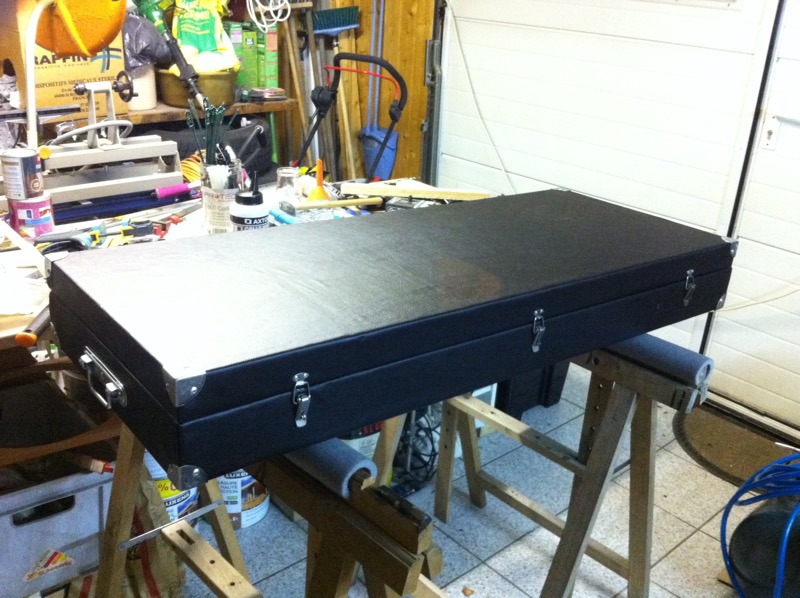 A really solid flightcase, 10mm Plywood, covered with fake leather
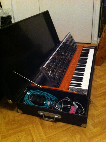 A nice place for my MAGMA to travel, plus some storage for pedals, cables and stuff
Appendix B: some original drawings
This are some inverted scans of my early drawings: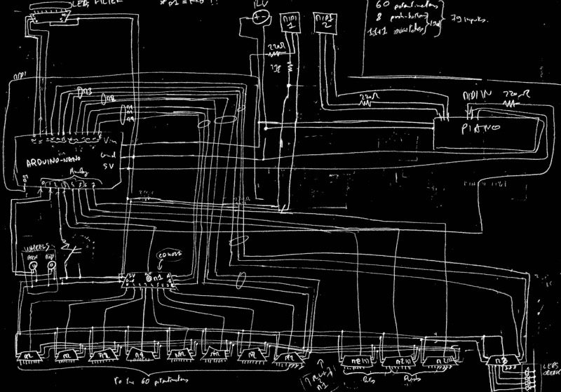 The multiplexing circuit
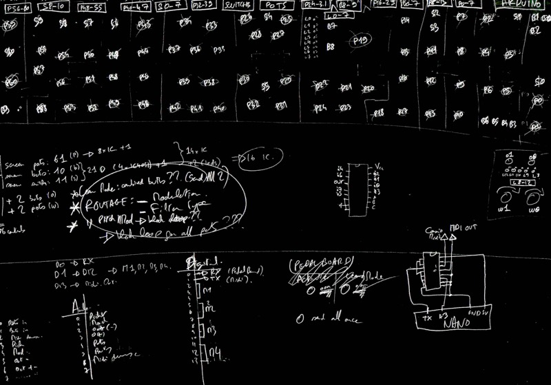 The emplacement of the potentiometers view from behind the panel
(used to locate pots during soldering and maintenance)
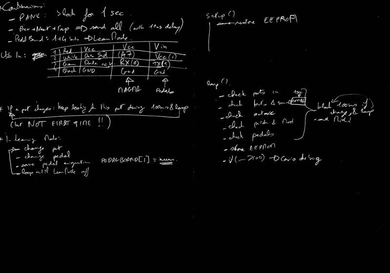 Some algorithmic notes
Thanks.
I would like to thanks my uncle for letting me work in his garage at full time for some weeks, he helped me a lot too, since he had a electronic training and professionnal experience.Thanks to you to have take the time to read my story of this adventure.
Don't hesitate to contact me via the "contact" tab on the top bar for any question of thoughts, I'm always happy to talk to people about music, electronics, woodworking, and so.
Have a nice day.
J.M.


© Copyright Josselin MARNAT 2013-2021 - Design & Content